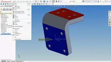
SOLIDWORKS is a powerful computer-aided design (CAD) software widely used in various industries for creating 3D models and assemblies. One fundamental operation in SOLIDWORKS is cutting parts, which involves removing material to create voids or separate components. In this article, we will provide a comprehensive guide on how to cut a part in SOLIDWORKS, covering various techniques and tools to achieve the desired results.
Understanding Cutting Operations in SOLIDWORKS
Cutting operations in SOLIDWORKS enable users to remove material from existing parts, creating cavities, holes, or separating components. These operations are crucial for designing complex models, creating assemblies, and manufacturing processes such as CNC machining. SOLIDWORKS offers several tools and features to accomplish cutting operations, including extrude cuts, revolve cuts, swept cuts, and more. Let’s explore some of these techniques in detail.
1. Extrude Cut
The extrude cut feature in SOLIDWORKS allows you to remove material by extruding a sketch in a specific direction. To perform an extrude cut:
- Create a sketch on the face or plane where you want to make the cut.
- Use sketch tools such as lines, arcs, and circles to define the geometry of the cut.
- Select the “Extruded Cut” tool from the Features toolbar.
- Choose the sketch you created in step 1 as the profile to cut.
- Set the desired depth and direction for the cut.
- Click “OK” to finalize the extrude cut.
2. Revolve Cut
The revolve cut feature revolves a sketch profile around an axis, removing material in a rotational manner. Follow these steps to perform a revolve cut:
- Create a sketch on a plane perpendicular to the axis of revolution.
- Draw the desired profile using sketch tools.
- Select the “Revolved Cut” tool from the Features toolbar.
- Choose the sketch you created in step 1 as the profile to cut.
- Define the axis of revolution by selecting an edge, axis, or sketch line.
- Set the desired angle and direction of the cut.
- Click “OK” to complete the revolve cut.
3. Swept Cut
The swept cut feature enables you to cut along a path defined by a sketch, removing material as it follows the trajectory. To perform a swept cut:
- Create a sketch defining the profile to be cut and a trajectory curve or path.
- Select the “Swept Cut” tool from the Features toolbar.
- Choose the sketch you created in step 1 as the profile to cut.
- Select the path sketch or curves to define the trajectory.
- Adjust additional settings such as twist options or guide curves if needed.
- Click “OK” to execute the swept cut operation.
Additional Tips and Techniques
To enhance your cutting operations in SOLIDWORKS, consider the following tips:
- Fillet and Chamfer: Use fillet and chamfer features to add rounded edges or beveled corners to your cut parts, improving aesthetics and functionality.
- Through All and Blind Cuts: SOLIDWORKS allows you to specify whether a cut should go through the entire part (through all) or stop at a specific depth (blind), giving you greater control over the cutting process.
- Split Feature: The split feature in SOLIDWORKS enables you to divide a part into separate bodies or components. This is useful for creating complex assemblies or analyzing individual components.
- Draft Analysis: Before performing cuts, utilize SOLIDWORKS’ draft analysis tool to check if your model has appropriate draft angles, ensuring easy part release from molds during manufacturing processes.
FAQ: How to Cut a Part in SOLIDWORKS?
1. How do I create a cut in SOLIDWORKS?
To create a cut in SOLIDWORKS, you can utilize various tools and features depending on the desired outcome. One common method is using the “Extruded Cut” feature. First, create a sketch on the desired face or plane where you want to make the cut. Then, use sketch tools such as lines, arcs, and circles to define the geometry of the cut. Next, select the “Extruded Cut” tool from the Features toolbar and choose the sketch as the profile to cut. Set the depth and direction for the cut, and click “OK” to finalize the operation. This method allows you to remove material by extruding the sketch in a specific direction.
2. Can I cut parts with rounded edges in SOLIDWORKS?
Yes, SOLIDWORKS provides features to cut parts with rounded edges. One approach is to use the “Fillet” feature. After creating the initial cut, you can select the edges you want to round and apply the fillet. This feature allows you to add a specific radius to the edges, resulting in rounded corners. Another option is to use the “Chamfer” feature, which creates beveled edges on your cut parts. By adjusting the parameters of the fillet or chamfer, you can achieve the desired level of rounding or beveling on your cut edges, enhancing both the aesthetics and functionality of your parts.
3. Can I create complex cuts in SOLIDWORKS?
Absolutely! SOLIDWORKS offers advanced tools to create complex cuts in your parts. One such tool is the “Swept Cut” feature. With this feature, you can cut along a path defined by a sketch, allowing for intricate and custom cuts. By creating a sketch that represents the profile you want to cut and a separate sketch that defines the path, you can execute a swept cut operation. This is particularly useful when you need to create curved or contoured cuts in your parts. Additionally, SOLIDWORKS provides options like guide curves and twist control within the swept cut feature, giving you even more flexibility to achieve complex and sophisticated cut designs.
4. Is it possible to cut through multiple parts simultaneously in SOLIDWORKS?
Yes, SOLIDWORKS allows you to cut through multiple parts simultaneously using the “Multi-Body Part” feature. This feature enables you to create multiple solid bodies within a single part file. By utilizing this functionality, you can perform cuts that extend through multiple bodies, thereby achieving cuts that affect several parts at once. To utilize the multi-body part feature, start by creating separate solid bodies within your part file. Then, apply the desired cut operation to one of the bodies, ensuring that it extends through the others. This capability is advantageous when designing complex assemblies or when you need to create features that span across multiple components.
5. Can I preview the cut results before executing the operation in SOLIDWORKS?
Yes, SOLIDWORKS provides a preview functionality that allows you to visualize the cut results before executing the operation. When performing a cut, you can enable the “Preview” option, which provides a real-time preview of how the cut will affect your part. This allows you to make any necessary adjustments or modifications to the cut parameters, ensuring the desired outcome. By visualizing the preview, you can verify the correctness of the cut and make any necessary refinements before finalizing the operation. This feature saves time and reduces the chance of errors, enhancing your overall design process in SOLIDWORKS.
6. Can I edit or modify a cut after it has been created in SOLIDWORKS?
Yes, SOLIDWORKS allows you to edit or modify cuts even after they have been created. To make changes to an existing cut, you can access the feature tree and locate the cut operation. By double-clicking on the cut feature, you can modify its parameters, such as depth, direction, or profile sketch. Additionally, you can adjust the size, shape, or location of the sketch associated with the cut. SOLIDWORKS offers a robust set of editing capabilities, empowering you to refine and customize your cuts as your design evolves, without the need to start from scratch.
7. Can I use imported geometry to perform cuts in SOLIDWORKS?
Yes, SOLIDWORKS supports the use of imported geometry to perform cuts. When working with imported models or assemblies, you can still apply cut features using the available cutting tools. Start by creating sketches or selecting existing geometry on the imported part where you want to make the cut. Then, utilize the appropriate cutting feature, such as extrude cut, revolve cut, or swept cut, and define the desired parameters. By leveraging the flexibility of SOLIDWORKS’ cutting tools, you can incorporate imported geometry seamlessly into your design process and achieve the desired cuts on imported parts.
Note: The above answers provide general guidance on performing cuts in SOLIDWORKS and may vary depending on the specific version and configuration of the software. Always refer to the SOLIDWORKS documentation and consult the software’s user interface for precise instructions and options.
Conclusion
Mastering the art of cutting parts in SOLIDWORKS is essential for creating intricate 3D models, assemblies, and preparing designs for manufacturing. This comprehensive guide has provided you with an overview of cutting operations in SOLIDWORKS, including extrude cuts, revolve cuts, swept cuts, and additional tips to enhance your cutting techniques. With practice and exploration of the various tools available, you can unlock the full potential of SOLIDWORKS and unleash your creativity in designing complex and precise parts.