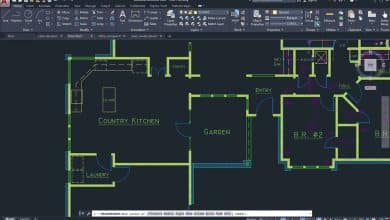
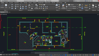
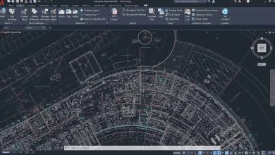
Welcome to our comprehensive FAQ on “Standard Unit Systems and Conventions in Architectural and Engineering CAD Drafting.” In this guide, we will delve into the essential aspects of computer-aided design (CAD) used in the fields of architecture and engineering. CAD is a powerful tool that revolutionizes the way professionals create, visualize, and communicate their designs.
Whether you are a seasoned architect, an aspiring engineer, or simply curious about CAD drafting, this FAQ provides detailed insights into the standard unit systems, conventions, and best practices that shape the world of architectural and engineering drawings.
From setting up the correct scale for architectural drawings to accurately representing various mechanical components, we will explore a wide range of topics to help you navigate the intricacies of CAD drafting with confidence and precision.
FAQ: Standard Unit Systems and Conventions in Architectural and Engineering CAD Drafting
1. What are the standard unit systems used in CAD drafting for architectural designs?
In architectural CAD drafting, the two most common unit systems are the imperial system (feet and inches) and the metric system (meters and centimeters). The choice of unit system often depends on the location and region of the project, as different countries may have their preferred conventions.
2. How do I set up the correct scale for an architectural drawing in CAD software?
To set up the correct scale for an architectural drawing in CAD software, you need to know the intended paper size and the scale factor. First, determine the scale ratio, such as 1/4″ = 1′-0″ for the imperial system or 1:50 for the metric system. Then, configure the drawing settings or page setup in the CAD software to match the desired scale.
3. What are the common standard dimensions for doors and windows in architectural CAD drafting?
Common standard dimensions for doors and windows in architectural CAD drafting vary depending on building codes and design preferences. In the United States, for example, a standard interior door is typically 3 feet wide by 6 feet 8 inches tall, while a standard double-hung window may be 3 feet wide by 5 feet tall. However, these dimensions may differ in other regions.
4. What is the standard line weight for various elements in architectural CAD drawings?
The standard line weight for various elements in architectural CAD drawings varies to create visual contrast and hierarchy. For instance, visible and strong lines (walls, doors) usually have a heavier weight, while hidden lines (interior features not directly visible) are lighter. Standard line weight conventions may include 0.5mm for visible lines, 0.3mm for hidden lines, and 0.7mm for borders and outlines.
5. How are floor plans typically dimensioned in architectural drafting using CAD?
In architectural drafting, floor plans are dimensioned using aligned and continuous dimensions. Distances between walls, doors, and windows are commonly specified, along with overall room dimensions. The dimensions are placed outside the floor plan and linked to the relevant elements through extension lines.
6. What are the standard text height and font styles used in architectural CAD drawings?
The standard text height in architectural CAD drawings is often defined based on the paper size and drawing scale. For example, text may have a height of 1/8″ (imperial) or 2.5mm (metric) for typical annotations. Font styles like Arial or Times New Roman are commonly used due to their readability, simplicity, and availability across platforms.
7. What are the recommended tolerances for various architectural elements in CAD drafting?
Recommended tolerances for architectural elements in CAD drafting depend on the project’s requirements and the level of precision needed. As a general guideline, a tolerance of ±1/16″ (imperial) or ±1.5mm (metric) is common for most architectural features, but critical components may require tighter tolerances.
8. How can I accurately represent different materials in architectural CAD drawings?
To accurately represent different materials in architectural CAD drawings, use appropriate hatch patterns, colors, or rendering techniques. For example, bricks might be represented with a specific hatch pattern, and different roof materials can be depicted using color gradients or texture fills.
9. What are the standard measurements for common architectural symbols used in CAD drafting?
Standard measurements for common architectural symbols in CAD drafting are often scaled to match the drawing’s overall dimensions. For example, a standard door symbol might be drawn at 3 feet wide, corresponding to a standard 3-foot wide door in the building.
10. What is the standard layering convention used for organizing architectural CAD drawings?
The standard layering convention in architectural CAD drafting involves creating separate layers for different types of elements, such as walls, doors, windows, furniture, text, dimensions, and annotations. This layer organization enhances drawing clarity and allows for easier control over visibility and editing.
11. How do I accurately represent stairs and ramps in architectural CAD drafting?
To accurately represent stairs and ramps in architectural CAD drafting, utilize specific symbols or linetypes that represent the components accurately. For stairs, show the risers, treads, and handrails as per the building’s design. Ramps should be represented with the correct slope and dimensions.
12. What are the standard measurements for common furniture elements in CAD drawings?
Standard measurements for common furniture elements in CAD drawings can vary depending on the furniture type and region. Common practice is to use standard furniture sizes and dimensions based on local industry standards or manufacturer catalogs.
13. How do I dimension and annotate elevations and sections in architectural CAD drafting?
To dimension and annotate elevations and sections in architectural CAD drafting, use aligned dimensions to indicate the height or depth of various elements. Add annotation to describe the materials, finishes, and other relevant information for each element on the elevation or section view.
14. What are the typical line types used for various elements in civil engineering CAD drafting?
In civil engineering CAD drafting, typical line types include continuous lines for visible objects like roads and buildings, dashed lines for hidden or obscured objects, and dotted lines for construction lines or boundaries. These line types enhance drawing clarity and convey specific meanings.
15. How are standard measurements and symbols represented for utility networks in civil CAD drafting?
Standard measurements and symbols for utility networks in civil CAD drafting are often depicted with specific linetypes and colors to differentiate between different types of utilities, such as water, gas, electricity, or telecommunications.
16. What are the standard dimensions for roadways and parking spaces in civil engineering CAD drawings?
Standard dimensions for roadways and parking spaces in civil engineering CAD drawings follow local road design standards and regulations. For example, a typical two-lane road may have a width of 12-16 meters, while parking spaces may be 2.4 meters wide and 5.5 meters long.
17. How are different types of mechanical fasteners represented in mechanical CAD drafting?
In mechanical CAD drafting, different types of mechanical fasteners, such as screws, nuts, and bolts, are often represented using specific symbols or standardized 3D models. The symbols or models should accurately depict the size and type of fastener used in the design.
18. What are the standard tolerances for various mechanical components in CAD drawings?
Standard tolerances for various mechanical components in CAD drawings are typically specified in engineering standards or based on the requirements of the specific project. Commonly, tolerances for mechanical components range from ±0.1mm to ±0.5mm, depending on the part’s function and criticality.
19. How do I accurately represent threads and screws in mechanical CAD drafting?
To accurately represent threads and screws in mechanical CAD drafting, use thread symbols or specific CAD features that create realistic 3D representations of threads. This helps convey essential information about the screw’s size and thread pitch.
20. What are the standard measurements and symbols used for electrical components in CAD drawings?
Standard measurements and symbols used for electrical components in CAD drawings depend on the specific component being represented. Common electrical symbols are used to depict items like switches, outlets, lights, and circuit breakers, while measurements are typically based on the manufacturer’s specifications.
21. What is the standard layer naming convention for mechanical CAD drawings, and how does it help organize the design?
The standard layer naming convention for mechanical CAD drawings involves using descriptive and logical names for different components and elements. For example, layers might be named “Dimensions,” “Annotations,” “Fasteners,” “Centerlines,” “Holes,” and so on. This convention helps organize the design by allowing easy visibility and management of specific elements. Each layer can be turned on or off as needed, making it simpler to work on specific parts without cluttering the drawing.
22. How are standard measurements and annotations represented for piping and plumbing systems in mechanical CAD drafting?
In mechanical CAD drafting for piping and plumbing systems, standard measurements and annotations are often represented using aligned dimensions and text annotations. Dimensions indicate the lengths, diameters, and angles of pipes and fittings, while annotations provide additional information, such as pipe materials and flow direction.
23. What are the common drawing views used for mechanical components in CAD drawings?
The common drawing views used for mechanical components in CAD drawings are the front view, top view, right-side view, and isometric view. Additional views, such as section views and detailed views, may be used to provide further clarity and information about specific parts of the component.
24. How are geometric tolerances specified for mechanical parts in CAD drafting?
Geometric tolerances are specified for mechanical parts in CAD drafting using standard symbols and annotations, such as concentricity, parallelism, and perpendicularity. These symbols are applied directly to the part’s features, and accompanying tolerances are provided to indicate the allowable variation from the ideal geometric shape.
25. What is the standard representation of surface finishes in mechanical CAD drawings?
The standard representation of surface finishes in mechanical CAD drawings is typically done using symbols from a surface finish symbol library. These symbols convey information about the required surface texture, roughness, and other manufacturing specifications.
26. How are standard measurements and symbols represented for HVAC (Heating, Ventilation, and Air Conditioning) systems in CAD drafting?
In HVAC CAD drafting, standard measurements and symbols are used to represent ducts, diffusers, grilles, and other components. Dimensions specify the duct sizes and lengths, while symbols represent the various components in the system.
27. What are the standard measurement units used for structural elements in architectural and civil CAD drawings?
The standard measurement units used for structural elements in architectural and civil CAD drawings are generally the same as the units used in the overall project, which can be either the imperial system (feet and inches) or the metric system (meters and centimeters).
28. How do I accurately represent different types of foundations in civil engineering CAD drafting?
To accurately represent different types of foundations in civil engineering CAD drafting, use specific symbols or linetypes for various foundation types, such as shallow foundations (footings), deep foundations (piles), or mat foundations. Ensure that the dimensions and details accurately match the engineering design.
29. What are the standard measurements and symbols used for landscape elements in architectural CAD drawings?
Standard measurements and symbols for landscape elements in architectural CAD drawings include representations for trees, plants, pathways, and other landscape features. Symbols help convey the type and size of each element, while dimensions provide information about distances and areas.
30. How are standard measurements and symbols represented for fire protection systems in architectural and civil CAD drafting?
In architectural and civil CAD drafting for fire protection systems, standard measurements and symbols are used to represent fire sprinklers, extinguishers, fire hoses, and other fire safety components. Symbols depict the location and type of each device, while annotations may include details like flow rates and pressure requirements.
31. What is the standard representation of reinforcement detailing in structural CAD drawings?
The standard representation of reinforcement detailing in structural CAD drawings involves using specific symbols and annotations to represent rebar shapes, sizes, and spacing. This helps communicate the reinforcement requirements for concrete elements effectively.
32. How are standard measurements and symbols represented for stormwater management in civil engineering CAD drafting?
In civil engineering CAD drafting for stormwater management, standard measurements and symbols are used to represent storm drains, culverts, retention basins, and other stormwater infrastructure. Symbols convey the type and size of each component, while dimensions specify their positions and dimensions.
33. What are the typical line types used for various mechanical systems in CAD drawings?
The typical line types used for various mechanical systems in CAD drawings include continuous lines for visible edges, dashed lines for hidden or obscured edges, and chain lines for alternate positions. Each line type helps distinguish different parts of the mechanical system in the drawing.
34. How do I accurately represent welding symbols in mechanical CAD drafting?
To accurately represent welding symbols in mechanical CAD drafting, use standardized welding symbols, such as fillet welds, groove welds, or plug welds. Place these symbols near the joint where the welding is required and include relevant dimensions and other specifications.
35. What are the standard measurements and symbols used for electrical wiring and devices in CAD drawings?
Standard measurements and symbols used for electrical wiring and devices in CAD drawings include symbols for outlets, switches, circuit breakers, and wires. These symbols help represent the layout and arrangement of electrical components in the design.
36. How are standard measurements and symbols represented for telecommunication systems in architectural and civil CAD drafting?
In architectural and civil CAD drafting for telecommunication systems, standard measurements and symbols are used to represent network cables, fiber optic lines, telephone connections, and other telecommunication components. Symbols convey the type and purpose of each element, while annotations provide additional details.
37. What are the common annotation styles for dimensioning in civil engineering CAD drawings?
Common annotation styles for dimensioning in civil engineering CAD drawings include aligned dimensions, radial dimensions, and angular dimensions. These annotation styles provide accurate measurements of distances, radii, and angles within the civil engineering design.
38. How do I accurately represent different types of beams and columns in structural CAD drafting?
To accurately represent different types of beams and columns in structural CAD drafting, use specific symbols or linetypes to differentiate between various shapes and sizes. Provide relevant dimensions and annotations to convey the beam and column sizes accurately.
39. What are the standard measurements and symbols used for elevators and escalators in architectural CAD drawings?
Standard measurements and symbols used for elevators and escalators in architectural CAD drawings include symbols representing elevator cars, shafts, and control panels. The symbols help illustrate the locations and dimensions of these vertical transportation elements.
40. How are standard measurements and symbols represented for solar energy systems in architectural and civil CAD drafting?
In architectural and civil CAD drafting for solar energy systems, standard measurements and symbols are used to represent solar panels, inverters, and related components. Symbols convey the orientation and tilt of the solar panels, while annotations may indicate power generation capacity and other system details.
Conclusion
We hope this comprehensive FAQ has been a valuable resource for gaining a deeper understanding of “Standard Unit Systems and Conventions in Architectural and Engineering CAD Drafting.” The world of CAD drafting is vast and ever-evolving, and with the knowledge gained here, you are now better equipped to tackle diverse design challenges with greater efficiency and accuracy.
By adhering to standard unit systems, layer naming conventions, and precise measurement techniques, you can ensure that your architectural and engineering CAD drawings are not only visually compelling but also compliant with industry standards and codes. Moreover, accurately representing various elements, from HVAC systems to landscape elements, helps convey your design intent effectively.
Remember, CAD drafting is a skill that improves with practice, so don’t hesitate to explore different features, experiment with various tools, and continually refine your techniques. As you embark on your CAD journey, stay curious, remain attentive to detail, and embrace the power of technology to bring your creative visions to life.
Thank you for joining us on this educational journey, and we wish you every success in your architectural and engineering endeavors!


