In the world of computer-aided design (CAD), AutoCAD is a powerful and versatile tool that has become an industry standard for creating precise and detailed technical drawings. One of the fundamental skills for any AutoCAD user is the ability to create 2D objects efficiently and accurately. In this comprehensive guide, we will explore the various techniques and tools available in AutoCAD to master 2D object creation, which is essential for professionals across various industries such as architecture, engineering, and product design.
Key Takeaways:
- Learn the importance of 2D drafting and design in AutoCAD.
- Understand how to create and work with linear and reference geometry.
- Discover techniques for creating curved and closed geometry objects.
- Gain insight into essential commands and editing tools for 2D object creation.
- Find resources for further learning and practice to enhance your AutoCAD skills.
I. Introduction to 2D Objects in AutoCAD
A. Overview of AutoCAD software
AutoCAD is a computer-aided design (CAD) software developed by Autodesk, used across a variety of industries for creating detailed technical drawings and designs. Since its introduction in 1982, AutoCAD has become an essential tool for architects, engineers, and designers. It offers a wide range of features and tools, enabling users to create accurate and detailed 2D and 3D drawings. AutoCAD’s versatility and compatibility with various file formats make it an industry standard for drafting and design.
The software’s user interface provides a workspace where users can create and modify drawings using a combination of commands, toolbars, and palettes. AutoCAD also supports customization, allowing users to tailor the software to their specific needs, preferences, and workflows. This adaptability contributes to AutoCAD’s popularity in various industries, from mechanical and electrical engineering to architecture and urban planning.
B. Importance of 2D drafting and design
2D drafting and design is an essential aspect of the design process across numerous industries. It involves creating technical drawings that represent an object or a structure from a two-dimensional perspective. These drawings provide crucial information about the dimensions, materials, and construction methods, serving as a blueprint for production, assembly, or construction.
In the digital age, 2D drafting has largely transitioned from manual drawing on paper to computer-aided drafting using software like AutoCAD. The shift to digital drafting offers numerous benefits, such as increased accuracy, efficiency, and ease of modification. Moreover, CAD software enables users to create detailed and precise drawings that can be easily shared, stored, and integrated into various systems.
Despite the growing popularity of 3D modeling, 2D drafting remains an essential skill for professionals in various fields. It is often the first step in the design process, providing a foundation for 3D models and simulations. Additionally, 2D drawings are still widely used for documentation, communication, and regulatory compliance, making them an indispensable part of the design and engineering workflow.
II. 2D Isometric Drawing in AutoCAD
A. Definition and purpose
2D isometric drawing is a type of technical drawing that represents a three-dimensional object in two dimensions. In isometric drawings, the three principal axes are equally inclined to the drawing plane, and all dimensions are drawn to the same scale. This method allows designers and engineers to visually represent 3D objects while maintaining their proportionality and relative positions, without the need for perspective.
The primary purpose of 2D isometric drawings is to provide a clear and accurate representation of an object’s form and dimensions. They are particularly useful for conveying complex shapes and spatial relationships that may be challenging to understand in a standard 2D drawing. Isometric drawings are widely used in various industries, such as engineering, architecture, and product design, as they provide a comprehensive understanding of an object’s structure and layout.
B. Benefits and applications
2D isometric drawings offer several benefits over traditional orthographic projections. By presenting an object in a pseudo-3D view, isometric drawings facilitate a more intuitive understanding of the object’s structure and spatial relationships. This enhanced visualization aids in design communication, collaboration, and decision-making.
Isometric drawings also enable designers to depict complex objects with greater clarity and precision than traditional 2D drawings. As a result, they are widely used in various industries to convey technical information, such as piping layouts, mechanical assemblies, and architectural floor plans. Furthermore, isometric drawings can be easily converted into 3D models, providing a valuable foundation for further design development and analysis.
C. Setting up an isometric drawing environment
AutoCAD provides tools and features to create and modify isometric drawings efficiently. To set up an isometric drawing environment, follow these steps:
- Activate isometric snap mode: This mode aligns the cursor with the isometric axes, allowing you to draw along the isometric planes. To enable isometric snap mode, type “SNAP” in the command line, then select “Isometric snap” in the Snap Type section of the Drafting Settings dialog box.
- Switch between isometric planes: AutoCAD allows you to switch between the three isometric planes (Top, Left, and Right) using the F5 key. This functionality enables you to draw on different isometric planes without changing the drawing’s overall perspective.
- Use isometric drawing tools: AutoCAD offers a range of isometric drawing tools, such as the Line, Circle, and Ellipse commands, that are adapted for isometric drafting. These tools simplify the process of creating isometric shapes and maintain the correct proportions and angles for the isometric perspective.
By setting up a dedicated isometric drawing environment in AutoCAD, you can efficiently create accurate and visually appealing isometric drawings that effectively communicate your design intent.
III. Linear and Reference Geometry
A. Overview and importance
Linear and reference geometry form the foundation of 2D drafting in AutoCAD. These geometric elements, such as lines, polylines, and multilines, are used to create a wide range of objects, from simple shapes to complex structures. Reference geometry, including construction lines, points, and rays, provides essential guidance for accurate and precise drafting. Mastering the creation and manipulation of linear and reference geometry is crucial for any AutoCAD user, as it enables efficient and accurate drafting, design communication, and documentation.
B. Creating lines
1. Line command
The Line command is a fundamental drawing tool in AutoCAD that allows you to create straight lines between two points. To use the Line command, type “LINE” or “L” in the command line, press Enter, and then specify the start and end points of the line. You can continue drawing connected lines by specifying additional points, and press Enter or Esc to end the line drawing sequence.
2. Construction techniques
There are several construction techniques for creating lines in AutoCAD. One common method is using coordinates to define the start and end points of a line. You can input absolute coordinates (X, Y) or relative coordinates (@X, Y) to create lines with precise dimensions and positions. Alternatively, you can utilize object snaps (OSNAP) to create lines that connect or align with existing objects, ensuring accurate and consistent geometry.
C. Creating polylines
1. Polyline command
Polylines are versatile drawing objects in AutoCAD that consist of connected line segments or arcs. The Polyline command allows you to create polylines with varying widths, linetypes, and vertex properties. To create a polyline, type “POLYLINE” or “PL” in the command line, press Enter, and specify the start point of the polyline. Then, add additional vertices by clicking or entering coordinates, and press Enter or Esc to complete the polyline.
2. Editing and modifying polylines
AutoCAD provides various tools for editing and modifying polylines, such as the PEDIT (Polyline Edit) command, which offers options for joining, breaking, and modifying polyline segments. You can also use the properties palette to change the polyline’s properties, such as width, linetype, and layer. Grips can be used to modify the polyline’s shape and size interactively by dragging vertices or segments.
D. Creating multilines
1. Multiline command
Multilines are composite drawing objects that consist of parallel lines, which can be used to represent walls, pipelines, or other entities with multiple parallel components. To create a multiline, type “MLINE” or “ML” in the command line, press Enter, and specify the start point of the multiline. Continue adding vertices by clicking or entering coordinates, and press Enter or Esc to complete the multiline.
2. Multiline styles and editing
Multiline styles control the appearance and properties of multilines, such as the number of parallel lines, offsets, colors, and linetypes. You can create and manage multiline styles using the “MLSTYLE” command. When editing multilines, you can use the MLEDIT (Multiline Edit) command to modify multiline segments, add or remove vertices, and change the multiline style. Grips can also be used for interactive editing and modification of multilines.
E. Freehand sketches
1. Sketch command
The Sketch command in AutoCAD allows you to create freehand drawings that resemble hand-drawn sketches. This command can be useful for creating rough outlines, concept sketches, or artistic illustrations within the software. To use the Sketch command, type “SKETCH” in the command line, press Enter, and then click and drag the cursor to draw the freehand sketch. The sketch will be created as a series of short line segments, approximating the path of the cursor.
2. Techniques for creating freehand sketches
When creating freehand sketches in AutoCAD, it’s important to maintain a steady hand and consistent pressure on the mouse or drawing tablet to achieve smooth and accurate results. You can adjust the sketch settings, such as the increment angle and the length of the line segments, to control the appearance and smoothness of the sketch. Additionally, you can utilize layers and object properties to manage and organize your sketches within the drawing.
F. Reference geometry
1. Construction lines
Construction lines are temporary lines used to guide the drawing process in AutoCAD. They extend infinitely in one or both directions and do not affect the final output or geometry of the drawing. Construction lines can be created using the “XLINE” command for infinite lines or the “RAY” command for semi-infinite lines. To create a construction line, type the respective command in the command line, press Enter, and specify the base point and direction of the line.
2. Points and point styles
Points are simple geometric objects in AutoCAD that represent a single location in the drawing. They can be used as reference markers, snap points, or geometric constraints. Points can be created using the “POINT” command and are displayed as a small dot or symbol based on the current point style. You can change the point style and appearance using the “DDPTYPE” command, which allows you to select from various symbols, sizes, and rotation options.
3. Ray and xline commands
The Ray and Xline commands are used to create reference geometry in AutoCAD. As mentioned earlier, a ray is a semi-infinite line that extends in one direction from a specified base point, while an xline is an infinite line that extends in both directions. These lines are useful for creating reference geometry that aligns with existing objects, guides the drawing process, or establishes geometric relationships between objects. To create a ray or xline, type the respective command in the command line, press Enter, and specify the base point and direction of the line.
IV. Curved and Closed Geometry
A. Overview and applications
Curved and closed geometry play a significant role in 2D drafting and design, as they help create smooth, continuous shapes and paths, which are often essential for aesthetic, functional, or manufacturing purposes. Common curved and closed objects in AutoCAD include arcs, circles, and curved polylines. These geometric elements are widely used in various applications, such as architecture, product design, and mechanical engineering, to create complex, organic shapes, or to define boundaries and paths.
B. Creating curved objects
1. Curved polyline segments
In AutoCAD, you can create curved polyline segments by adding arc segments to an existing polyline. To do this, use the Polyline command and enter “A” for the Arc option, then specify the arc’s endpoint or radius. You can also create curved polyline segments by converting existing polyline segments into arcs using the PEDIT (Polyline Edit) command and selecting the “Spline” or “Fit” options.
2. Fillets and chamfers
Fillets and chamfers are tools in AutoCAD that create smooth transitions between two intersecting lines or polyline segments. A fillet creates a rounded corner, while a chamfer creates a beveled edge. To create a fillet or chamfer, use the “FILLET” or “CHAMFER” command, specify the desired radius or distance, and select the two lines or polyline segments to be joined. These tools are particularly useful for creating smooth, continuous paths and shapes in 2D drafting and design.
C. Creating arcs
1. Arc command
The Arc command in AutoCAD allows you to create curved segments defined by a center point, radius, and start and end angles. To create an arc, type “ARC” in the command line, press Enter, and specify the necessary parameters, such as the center point, radius, start angle, and end angle. You can also create arcs using alternative methods, such as specifying the start point, endpoint, and a point along the arc.
2. Arc construction techniques
There are several construction techniques for creating arcs in AutoCAD. Some common methods include using coordinates to define the arc’s center, start, and end points, or using object snaps (OSNAP) to create arcs that connect or align with existing objects. Additionally, you can utilize the “ARC” command’s various options, such as “Center,” “Angle,” “Direction,” and “Radius,” to create arcs with specific geometric properties and relationships.
D. Creating circles
1. Circle command
The Circle command in AutoCAD enables you to create circles defined by a center point and radius or diameter. To create a circle, type “CIRCLE” or “C” in the command line, press Enter, and specify the center point and radius or diameter. Circles can also be created using alternative methods, such as specifying two or three points on the circle’s circumference.
2. Circle construction methods
Various construction methods can be used to create circles in AutoCAD. One common technique is using coordinates to define the circle’s center and radius or diameter. You can also use object snaps (OSNAP) to create circles that align with existing objects or geometric constraints. Furthermore, you can create circles tangent to existing objects by using the “TTR” (Tangent, Tangent, Radius) or “TTT” (Tangent, Tangent, Tangent) options available in the Circle command.
E. Creating donuts
1. Donut command
The Donut command in AutoCAD allows you to create closed, filled, circular shapes with a specified inner and outer diameter. To create a donut, type “DONUT” in the command line, press Enter, and specify the inner diameter, outer diameter, and center point. Donuts are essentially closed polylines with a solid fill, and can be used to represent circular objects with a hollow center, such as washers or gaskets.
2. Applications and use cases
Donuts are useful in various applications, such as architectural design, mechanical engineering, and electrical schematics, where they can represent objects like openings, cutouts, or filled areas. They are also commonly used for annotation purposes, where they can serve as background masks or highlight specific areas within a drawing.
F. Creating ellipses
1. Ellipse command
The Ellipse command in AutoCAD enables you to create elliptical shapes defined by a center point, major axis, and minor axis. To create an ellipse, type “ELLIPSE” or “EL” in the command line, press Enter, and specify the center point, major axis endpoint, and minor axis distance or ratio. You can also create elliptical arcs by using the “Arc” option within the Ellipse command.
2. Editing and modifying ellipses
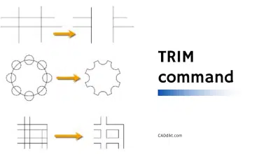
AutoCAD provides various tools for editing and modifying ellipses, such as the properties palette, which allows you to change the ellipse’s layer, color, linetype, and other properties. Grips can be used to interactively modify the ellipse’s shape and size by dragging the center point, major axis endpoint, or minor axis distance. Additionally, you can use standard editing commands, such as “TRIM,” “EXTEND,” and “FILLET,” to modify ellipses in relation to other objects in the drawing.
G. Creating splines
1. Spline command
The Spline command in AutoCAD allows you to create smooth, continuous curves that pass through a series of specified points, known as control points or fit points. To create a spline, type “SPLINE” in the command line, press Enter, and specify the control points or fit points. Splines can be created as either NURBS (Non-Uniform Rational B-Spline) curves or cubic splines, depending on the desired level of smoothness and control.
2. Spline construction and editing techniques
AutoCAD offers various tools and techniques for constructing and editing splines. You can add, remove, or modify control points or fit points using the properties palette, grips, or the “PEDIT” (Polyline Edit) command. You can also adjust the spline’s degree, knot values, and weights to control its smoothness, curvature, and continuity. Additionally, you can use standard editing commands, such as “TRIM,” “EXTEND,” and “FILLET,” to modify splines in relation to other objects in the drawing.
H. Creating helixes
1. Helix command
The Helix command in AutoCAD enables you to create 2D or 3D spiral shapes with a specified base point, radius, height, and number of turns. To create a helix, type “HELIX” in the command line, press Enter, and specify the necessary parameters. You can utilize a helix as a path for sweeping an object to generate a specific shape. For instance, sweeping a circle along a helix path can result in a solid model of a spring..
2. Applications and use cases
Helixes are commonly used in various applications, such as mechanical engineering, product design, and architecture, where they can represent objects like springs, coils, or spiral staircases. They are also useful in creating complex 2D or 3D paths for modeling or simulation purposes, such as toolpaths for CNC machining or motion paths for animations.
I. Creating regions
1. Region command
The Region command in AutoCAD allows you to create 2D, planar, closed areas from existing objects, such as lines, polylines, circles, arcs, or splines. To create a region, type “REGION” in the command line, press Enter, and select the objects that define the boundary of the region. Regions can be used for various purposes, such as calculating areas, performing Boolean operations, or creating solid models in 3D.
2. Editing and modifying regions
Regions can be edited and modified using standard editing commands, such as “MOVE,” “ROTATE,” “SCALE,” and “MIRROR.” Additionally, you can perform Boolean operations, such as “UNION,” “SUBTRACT,” or “INTERSECT,” on regions to create new shapes or modify existing ones. For example, you can use regions to find the overlapping area between two objects, or to subtract one object from another. Note that when editing regions, you may need to convert them back into their original objects (lines, polylines, etc.) using the “EXPLODE” command, and then recreate the region after making the desired modifications.
V. Conclusion
A. Recap of key concepts
Throughout this article, we have explored various aspects of creating 2D objects in AutoCAD, including the importance of 2D drafting and design, setting up an isometric drawing environment, and working with linear and reference geometry. We also covered creating curved and closed geometry, such as arcs, circles, donuts, ellipses, splines, and regions, along with their respective commands and construction techniques. Understanding these concepts and mastering the tools provided by AutoCAD is essential for creating accurate, efficient, and visually appealing 2D drawings and designs.
B. Importance of mastering 2D object creation in AutoCAD
Mastering the creation of 2D objects in AutoCAD is vital for professionals in various fields, such as architecture, engineering, product design, and manufacturing. A strong foundation in 2D object creation allows you to effectively communicate design ideas, create accurate and detailed technical drawings, and streamline the design process. Furthermore, a deep understanding of 2D object creation techniques will enable you to transition seamlessly into more advanced topics, such as 3D modeling and rendering, as well as improve your overall proficiency in AutoCAD.
C. Further resources for learning and practice
To further develop your skills in creating 2D objects in AutoCAD, you can explore a variety of resources available online and offline. Autodesk, the developer of AutoCAD, offers comprehensive documentation, tutorials, and forums where you can ask questions and seek guidance from experts. Additionally, you can find numerous online courses, video tutorials, and books that cover various aspects of 2D object creation and other AutoCAD topics.
Another effective way to improve your AutoCAD skills is by practicing regularly. Create sample drawings, explore new commands and techniques, and apply them to real-world projects. By continually learning and practicing, you will become a proficient and confident AutoCAD user, ready to tackle any design challenge that comes your way.
Conclusion
By following this comprehensive guide, you will gain a deep understanding of how to create 2D objects in AutoCAD and the various tools and techniques available for drafting and design. Mastering these skills is not only essential for your growth as a professional in your respective field, but it also provides a solid foundation for exploring more advanced topics in AutoCAD, such as 3D modeling and rendering.
Remember that learning and mastering any skill requires time, dedication, and consistent practice. Continually explore new tools, techniques, and resources, and apply the knowledge you gain to real-world projects. As you progress in your journey with AutoCAD, you will find that mastering 2D object creation will undoubtedly make you a more proficient, versatile, and confident designer, ready to tackle any challenge that comes your way.